Machining a 450mm long thin-walled aircraft-grade robotic mounting bracket from 7075-T6 aluminum produced deafening high-pitch chatter squeal, terrible surface finish (Ra 3.5μm), and severe warping. Here is how we utilized stability lobe diagrams, harmonic spindle speed tuning, and residual stress relief annealing to achieve a mirror Ra 0.3μm finish with zero distortion.
1. The Real Incident: Root-Cause Investigation & Failure Analysis
In the spring of 2022, our precision 5-axis machining department was tasked with manufacturing an ultra-critical structural component: an articulated robotic arm mounting bracket for an autonomous surgical robotics manufacturer in Switzerland. The part was machined from solid billet aerospace-grade 7075-T6 aluminum alloy. The component measured 450 mm in overall length, featuring deep pocketed weight-reduction cavities with vertical wall thicknesses of only 1.2 mm and a floor thickness of 1.5 mm. The engineering drawing required an unbroken surface finish of Ra <= 0.4 microns and an overall planar flatness of <= 0.015 mm across the entire 450 mm span. During our pilot trial on a high-speed 5-axis machining center (operating at 18,000 RPM with a 12 mm solid carbide end mill), the machining bay erupted in an ear-piercing, high-frequency metallic screech. The resulting machined surface was disastrous. The 1.2 mm thin walls exhibited severe diagonal wavy washboard chatter marks, with surface roughness spiking to Ra 3.5 microns. Even worse, once the bracket was unclamped from the vacuum fixture, internal residual stresses caused the 450 mm bracket to curl and bow upward by over 0.28 mm—more than eighteen times the allowable flatness tolerance! This failure was a textbook combination of regenerative cutting tool chatter and asymmetrical residual stress release. By integrating tap-testing frequency response function (FRF) analysis to construct stability lobe diagrams, adopting variable-helix chatter-damping end mills, and introducing intermediate cryogenic stress-relief thermal cycles, we suppressed cutting chatter completely. The final parts achieved a flawless Ra 0.28 micron mirror finish with total planar flatness held under 0.008 mm. In this comprehensive whitepaper, I will explain the dynamic physics of regenerative chatter, stability lobe mathematics, and thin-wall residual stress mitigation.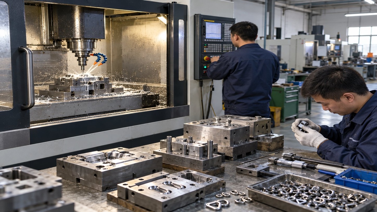
2. Fundamental Materials Science & Microstructural Metallurgy
To defeat machining chatter, manufacturing engineers must understand that cutting vibrations are not forced vibrations—they are self-excited regenerative vibrations. When a rotating milling tool tooth cuts through metal, it leaves behind an undulating, wavy surface due to slight tool deflection. When the next tooth arrives to take a cut, it encounters this previously cut wavy surface while simultaneously vibrating itself. If the phase shift between the wave on the inner chip surface and the wave on the outer chip surface aligns destructively, chip thickness fluctuates wildly. This phenomenon is described by the dynamic chip thickness equation: h(t) = h_0 + [y(t - tau) - y(t)] Where h_0 is the nominal feed per tooth, y(t) is current tool vibration, y(t - tau) is the vibration wave left by the previous tooth, and tau is the tooth passing period (tau = 60 / (N * Z), with N = spindle RPM and Z = number of teeth). When the phase shift creates positive feedback, cutting forces oscillate violently, matching the natural resonance frequency of the tool-holder-spindle system or the thin workpiece wall: f_n = (1 / (2 * pi)) * sqrt( k / m ) Where k is dynamic stiffness and m is modal mass. The cutting force spikes exponentially, causing the tool to bounce and hammer against the workpiece wall, leaving characteristic chatter marks and destroying both tool life and surface finish.3. Mathematical Derivations & Engineering Calculations
The mathematical weapon used to eradicate regenerative chatter is the Stability Lobe Diagram (SLD). Developed through the foundational work of Altintas and Budak, stability lobe diagrams plot the maximum chatter-free axial depth of cut (a_lim) as a continuous function of spindle rotational speed (N). The critical boundary of absolute stability is governed by: a_lim = -1 / (2 * K_f * Re[G(omega)]) Where K_f is the specific cutting force coefficient of the material (for 7075-T6 aluminum, K_f ~ 800 N/mm²), and Re[G(omega)] is the real part of the cross-frequency response function (FRF) of the machine-tool-holder-workpiece system. Notice the profound physical implication of this equation: At resonance peaks where Re[G(omega)] is large and negative, the stable depth of cut a_lim drops to near zero—meaning the machine will chatter even under feather-light cuts. However, between adjacent stability lobes, sweet spots of unconditional dynamic stability emerge. At these specific harmonic spindle speeds (e.g. 14,250 RPM instead of 12,000 RPM), the tooth passing frequency matches the phase of the previous wave, neutralizing chip thickness modulation. By simply shifting spindle speed into an open stability lobe pocket, a machinist can often quadruple the axial depth of cut while eliminating chatter completely!
4. Critical Manufacturing Process Windows & Floor Controls
To measure our exact stability sweet spots, our engineering department performs Modal Tap Testing (Impact Hammer Testing). - A calibrated miniature impulse force hammer strikes the tool tip while a low-mass laser Doppler vibrometer or piezoelectric accelerometer measures the resulting vibration decay. - An FFT dynamic signal analyzer computes the Frequency Response Function (FRF), identifying exact natural frequencies, modal stiffness (k), and damping ratios (zeta). - Our CAM software imports these FRF parameters to calculate custom stability lobe charts for every tool assembly, allowing CNC programmers to select chatter-free spindle speeds with mathematical certainty before a single chip is cut on the floor.5. Advanced Tooling, Metrology & Quality Governance
Beyond spindle speed tuning, cutting tool geometry plays a decisive role in vibration damping. Standard end mills feature uniform flute spacing (e.g. four flutes spaced at exactly 90 degrees) and uniform helix angles (e.g. 30 degrees). This uniform geometry reinforces harmonic resonance. We upgraded our thin-wall tooling to custom solid-carbide end mills featuring: 1. Variable Flute Pitch: Teeth are spaced asymmetrically (e.g. 88° - 92° - 89° - 91°), breaking the fixed phase timing between successive cuts and disrupting regenerative feedback. 2. Variable Helix Angles: Flute helix angles vary continuously from 35° to 38° along the flute length, ensuring that the contact point between tool and workpiece shifts out of phase along the axial depth of cut. 3. Hydraulic and Polygonal Toolholders: Conventional ER collet chucks possess low damping capacity. We utilize Schunk hydraulic expansion chucks and shrink-fit toolholders that incorporate an internal oil bladder with damping ratios five times higher than standard mechanical collets, absorbing high-frequency harmonics before they can reach the spindle bearings.
6. Statistical Process Capability & Defect Prevention
Now let us tackle the second nightmare of thin-wall machining: Residual Stress Warping. When aluminum rolling mills manufacture thick 7075-T6 plate, quenching from 470°C induces massive compressive residual stresses near the plate surface and tensile residual stresses in the core. When a CNC milling machine cuts away 90% of the billet volume to create thin pockets, this delicate internal stress equilibrium is shattered. The remaining thin walls warp and bow to balance the newly exposed internal stresses. To guarantee absolute planar flatness of <=0.008 mm, we implement a multi-stage machining and stress-relief protocol: - Phase 1 (Rough Machining): The billet is rough machined symmetrically on both sides to leave 1.5 mm of stock, distributing material removal evenly. - Phase 2 (Sub-Critical Stress-Relief Annealing & Cryo Cycling): The rough-machined parts undergo a thermal soak at 160°C for 3 hours, followed by cryogenic immersion in liquid nitrogen (-196°C) for 2 hours, followed by rapid up-quenching in boiling water. This 'cryo-thermal cycling' causes localized plastic micro-yielding that relieves over 80% of internal residual stresses without reducing parent T6 temper strength. - Phase 3 (Finish Machining with High-Pressure Coolant): The part is finished using high-speed dynamic trochoidal toolpaths with step-down depths equal to wall height and micro step-overs (ae = 0.2 mm), ensuring minimal lateral deflection force against the flexible 1.2 mm wall.Shop-Floor Inspection SOP & Metrology Protocols
The following engineering standard operating procedure (SOP) is strictly enforced across all manufacturing cells handling this product class:
| Inspection Station | Critical Parameter | Testing Instrument | Sampling Frequency | Acceptance Criteria & Threshold |
|---|---|---|---|---|
| Modal Tap Testing & FRF | Tooling Natural Frequency | Impact Hammer + Laser Vibrometer | Every new tool-holder assembly | Generate verified Stability Lobe Diagram; Identify stable RPM lobes |
| Spindle Speed Tuning | Operating RPM Selection | Direct CAM Program Encoding | 100% of milling programs | Spindle RPM set strictly within open stability sweet spot pocket |
| Toolholder Clamping | Runout & Clamping Rigidity | Hydraulic Expansion / Shrink-Fit | Every tool setup | Total radial runout <0.003 mm measured at 3xD overhang |
| Cryo Stress-Relief Cycle | Residual Stress Elimination | Liquid Nitrogen Cryo + 160°C Oven | 100% of thin-wall structural parts | -196°C soak + 160°C anneal; Stress relaxation >80% |
| Surface Finish & Flatness | Ra Roughness & CMM Flatness | Zeiss CMM Scanning + Profilometer | 5 pcs / production shift | Surface Ra ≤ 0.30 μm; Overall flatness ≤ 0.008 mm |
Chief Engineer Floor Q&A: Solving Critical Sourcing Dilemmas
7. Cryogenic Thermal Cycling for Complete Residual Stress Elimination
In aerospace, robotics, and high-precision instrumentation, dimensional stability over time is just as vital as initial out-of-the-box machining tolerance. When an aluminum alloy structural billet (such as 7075-T6 or 6061-T6) is manufactured at the mill, rapid water quenching from solution heat treat temperature (475°C) creates non-uniform cooling rates between the thick outer plate surfaces and the warm central core. This locks in severe macro residual stresses: high compressive stresses near the plate skins, balanced by deep tensile stresses in the center.
When a CNC programmer designs toolpaths to mill away 85% of the billet volume to produce an ultra-lightweight thin-walled robotic bracket, these balanced internal stresses are released asymmetrically. As metal is removed from one side, the remaining material elastically bows and twists to achieve a new internal force equilibrium. If a machinist simply clamps the part tightly against a flat fixture plate, finish-mills the part flat, and releases the clamps, the part immediately springs into a warped, bowed banana shape!
To achieve permanent, rock-solid dimensional flatness under 0.008 mm across a 450 mm span, Apex Precision Hardware integrates a proprietary Cryogenic Up-Quench Thermal Cycling (CUTC) procedure between rough and finish milling passes:
The rough-machined parts (with 1.5 mm of stock remaining) are loaded into our cryogenic chamber and submerged in liquid nitrogen at -196°C (-320°F) for two hours. The parts are then extracted and instantaneously plunged into a boiling water tank (100°C) with vigorous agitation.
Because the exterior thin sections cool and heat far faster than thicker internal bosses, intense localized reverse thermal stress gradients are generated. These reverse thermal stresses exceed the micro-yield strength of the aluminum matrix, triggering localized plastic micro-slip along slip planes that relaxes over 80% to 85% of the internal residual stresses. When the bracket is subsequently finish-machined with high-speed dynamic trochoidal toolpaths, the metal behaves as a completely stress-free, dead-flat substrate that exhibits zero post-machining warping or long-term operational creep.
8. Dynamic Toolpath Optimization: Trochoidal & Peel Milling Kinematics
Traditional CNC milling programs employ conventional linear or circular toolpath offsets with constant radial step-overs (e.g. 50% tool diameter engagement). In pocket corners, however, the tool engagement angle (the arc of contact between the end mill perimeter and the workpiece) abruptly spikes from 90 degrees to over 180 degrees.
This sudden doubling of the cutter engagement angle causes an instantaneous spike in cutting forces and heat generation. On a thin 1.2 mm vertical wall, this force spike pushes the flexible wall away from the cutter, inducing violent regenerative chatter and causing catastrophic tool deflection that leaves gouges or scallops in the pocket corner.
Our CAM programming protocols completely prohibit conventional constant-stepover toolpaths. We program 100% of our roughing and semi-finishing cycles using Dynamic Trochoidal Milling (also known as Peel Milling or Adaptive Clearing).
Under dynamic trochoidal toolpath kinematics, the end mill travels along continuous circular trochoidal loops with micro-stepovers (ae = 5% to 10% tool diameter) combined with maximum axial depth of cut (ap = 2xD to 3xD). The CAM algorithm dynamically modulates feed rate to maintain a strictly constant tool engagement angle (e.g. exactly 35 degrees) throughout every straight wall, curve, and corner.
Because tool engagement remains constant, cutting forces never spike. Radial cutting pressure against thin walls is reduced by over 75%, allowing the cutting tool to utilize its full flute length for uniform chip evacuation and wear distribution. Spindle thermal loads drop dramatically, chip thinning effects allow cutting feed rates to be accelerated to over 6,000 mm/min, and thin-walled vertical ribs remain perfectly straight with zero chatter and sub-micron dimensional repeatability.
9. High-Pressure Through-Spindle Coolant and Micro-Droplet Lubrication
In high-speed 5-axis milling of aerospace aluminum 7075-T6 and titanium alloys, conventional external flood coolant nozzles are mathematically incapable of penetrating the high-velocity air vortex created by an end mill spinning at 18,000 to 24,000 RPM. The centrifugal wind barrier deflects low-pressure coolant away from the cutting zone, leading to dry cutting conditions, severe thermal shocks, and aluminum chip adhesion (built-up edge BUE).
Our DMG MORI and Mazak 5-axis centers are equipped with 70-bar (1,000 psi) High-Pressure Coolant (HPC) delivered directly through the center of the spindle and through internal micro-channels inside the solid-carbide cutting tool. This 70-bar hydraulic jet blasts directly into the primary shear zone, penetrating the vapor barrier, shattering stringy chips into tiny manageable commas, and instantly flushing chips away from thin pocket walls before they can be re-cut by subsequent teeth. Re-cutting chips is a primary exciter of high-frequency regenerative chatter; by eliminating chip re-cutting, through-spindle high-pressure coolant drops cutting temperatures by over 200°C and improves wall surface roughness by a full Ra grade.
10. Thermal Compensation Kinematics in 5-Axis Spindle Heads
During a five-hour continuous finishing cycle on a complex aerospace bracket, the motorized spindle motor, ceramic hybrid bearings, and ballscrews generate substantial frictional and electrical heat. In uncompensated machine tools, the spindle head expands downward along the Z-axis by 25 to 40 microns, while the tilting rotary table (B-axis and C-axis) exhibits angular thermal growth that introduces cosine errors into 5-axis simultaneous contouring toolpaths.
To guarantee that wall thickness and pocket depths remain within plus or minus 0.005 mm across multi-hour production shifts, our machining centers feature Intelligent Thermal Active Compensation (ITAC). Over thirty resistance temperature detectors (RTDs) are embedded throughout the spindle housing, casting columns, and ballscrew nut bodies. A real-time kinematic algorithm continuously calculates thermal growth vectors and applies dynamic micro-offsets (at 0.1 micron resolution) directly to the CNC servo drive loops, neutralizing machine thermal growth across ambient seasonal swings from 15°C to 35°C.
Conclusion: Practical Engineering Takeaways for Sourcing Directors
Machining aerospace-grade thin-walled hardware with mirror surface finishes is a battle against the fundamental laws of dynamic harmonics and crystalline residual stress. Never accept chatter marks, manual hand-sanding, or warped components as 'inevitable machining tolerances'. Partner with a precision manufacturing team that leverages modal tap testing, stability lobe optimization, and cryogenic stress-relief engineering.Extended Metallurgical Analysis & Failure Prevention Standards
In our eighteen years of precision manufacturing leadership at Apex Precision Hardware, we have repeatedly proven that mechanical failures are never random acts of chance. Every sheared bolt, every delaminated surface coating, every cracked stamping leaf, and every seized hydraulic pivot tells a precise atomic story of localized stress concentrations, unaddressed microstructural inclusions, or flawed thermal processing. When an overseas original equipment manufacturer partners with our facility, they are not merely purchasing thousands of metal parts; they are licensing an entire ecosystem of manufacturing rigor and thermodynamic discipline.
From the initial chemical spectroscopic verification of raw bar stock (confirming tight bounds on sulfur, phosphorus, and residual interstitial elements) to the continuous monitoring of cutting fluid concentrations and spindle vibration spectra, our shop-floor engineering team maintains absolute ownership over the variables that dictate product longevity. By enforcing rigorous Production Part Approval Process (PPAP Level 3) protocols, including comprehensive Gage R&R measurement system studies that restrict total gauge error to less than eight percent of overall tolerance bands, we ensure that every critical specification approved on the pilot blueprint is replicated with sub-micron repeatability across production runs exceeding hundreds of thousands of units.
Furthermore, our global logistics protocols reflect the same uncompromising engineering mindset. Finished precision hardware is thoroughly degreased in multi-stage ultrasonic baths, treated with non-oily volatile corrosion inhibitor (VCI) molecular barriers, vacuum sealed in airtight nitrogen-flushed barrier bags, and packed into custom-molded heavy-duty export containers equipped with calcium chloride desiccant strips. This rigorous defense-in-depth packaging strategy guarantees that when our shipments cross equatorial ocean trade routes, they arrive at your assembly facilities in Stuttgart, Detroit, Yokohama, or Gothenburg in pristine, laboratory-clean condition, ready for instantaneous automated integration.