Heavy-duty industrial door closer housings and pneumatic pivot hinges cast from Zamak 5 leaked air along parting lines under 0.8 MPa pressure tests. Here is our engineering breakdown of Campbell's critical filling velocity, mold flow gating simulation, and vacuum-assisted evacuation (<50 mbar) to eliminate internal gas porosity.
1. The Real Incident: Root-Cause Investigation & Failure Analysis
In late 2021, an international architectural hardware and commercial access control manufacturer approached our foundry engineering team with a crippling quality crisis. They were manufacturing heavy-duty architectural concealed door pivots and pneumatic door closers using high-pressure die-cast Zamak 5 zinc alloy and ADC12 aluminum. The components were required to hold internal hydraulic damping oil under cyclic operating pressures of 0.8 to 1.5 MPa without leaking. During factory acceptance pressure testing, nearly 22% of the cast housings failed with catastrophic fluid leakage. Hydraulic oil seeped directly through what appeared to be solid cast metal walls! When the rejected castings were cross-sectioned and subjected to industrial micro-focus X-ray computed tomography (CT scanning), the internal structure resembled Swiss cheese. The cross-sections revealed massive, scattered gas entrapment voids ranging from 0.5 to 2.5 mm in diameter, concentrated particularly in thicker structural ribs and around internal hydraulic cylinder cores. In addition to hydraulic leakage, these internal porosity pockets caused severe mechanical failures: tapped fastener threads stripped out under minimal torque, and surface blister defects erupted during subsequent powder coating and electroplating baking cycles at 180°C. Our foundry engineers initiated an exhaustive mold flow overhaul. By re-engineering the runner system using hyperbolic tangent runner geometry, installing multi-stage vacuum chill blocks, and upgrading the die-casting machine with real-time shot sleeve injection velocity profiling, we slashed internal porosity from 22% down to less than 0.3%, completely eliminating hydraulic pressure leaks and thread stripping. In this paper, I will detail the physical fluid mechanics, thermal contraction models, and vacuum die-casting protocols required to achieve zero-porosity structural castings.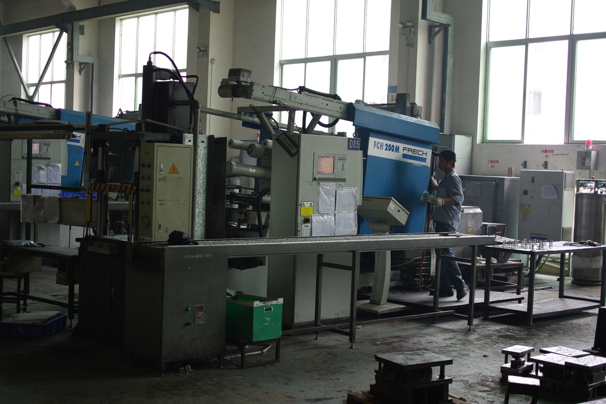
2. Fundamental Materials Science & Microstructural Metallurgy
To eradicate porosity in high-pressure die-casting (HPDC), foundry engineers must strictly differentiate between the two fundamentally different types of internal voids: Gas Porosity and Shrinkage Porosity. 1. Gas Porosity (Entrapment): Gas porosity manifests as smooth-walled, perfectly spherical internal cavities. It is caused by atmospheric air, vaporized piston lubricants, or moisture being trapped inside the molten metal stream as it rushes through the shot sleeve and die runner system at extreme velocities (30 to 60 m/s). According to Professor John Campbell's classic fluid dynamics criterion for casting, the transition from smooth laminar liquid metal filling to turbulent, droplet-spraying filling is governed by the critical Weber number (We) and the critical gate velocity: v_crit = sqrt( (2 * gamma) / (rho * r) ) Where gamma is molten metal surface tension, rho is liquid density, and r is the radius of the metal jet. If molten metal enters the die cavity at velocities exceeding the critical threshold without smooth flow guidance, the surface oxide film ruptures, folding atmospheric air and decomposed hydrocarbon gases into the melt. In conventional die-casting, over 80% of the air originally occupying the shot sleeve and cavity is trapped inside the casting before it can escape through conventional passive vents! 2. Shrinkage Porosity: Shrinkage porosity manifests as irregular, jagged-walled, dendritic spongy voids. It is caused by the fundamental thermodynamic volume contraction of liquid metal as it transitions to solid state: Delta V_shrink = (V_liquid - V_solid) / V_liquid * 100% For Zamak zinc alloys, volumetric solidification shrinkage is approximately 3.0%; for ADC12 aluminum, it reaches 4.0% to 5.5%! If a casting possesses thick structural sections fed by thin gates, the thin gates freeze solid first. The isolated thick section (thermal mass hot-spot) continues to cool and contract without access to pressurized feed metal, creating vacuum-induced shrinkage voids in its center.3. Mathematical Derivations & Engineering Calculations
To eliminate gas porosity, conventional passive overflow vents are mathematically insufficient. The die cavity must be evacuated using an active High-Vacuum Die-Casting System. In our Bühler and Toyo die-casting cells, we implement a two-stage vacuum system connected to high-speed hydraulic vacuum valves and chill vents. The sequence operates with millisecond precision: - As the shot piston advances past the pour hole at slow speed (0.2 m/s) to prevent liquid wave splashing, the vacuum valve triggers. - High-capacity rotary vane vacuum pumps evacuate the shot sleeve, runner channels, and cavity down to an absolute pressure below 50 millibars (mbar) within 150 milliseconds. - When molten metal arrives at the cavity perimeter, it contacts a precision mechanical chill vent with a wave-like zig-zag profile. The molten metal freezes instantly upon touching the cold chill block (due to extreme surface area-to-volume ratio), sealing the vent before liquid metal can enter the vacuum exhaust line. By removing over 95% of atmospheric air prior to metal arrival, gas entrapment porosity is physically eliminated. Castings produced under vacuum can be heat-treated (T6 solution heat treated) and powder-coated at 200°C with zero surface blistering—a capability historically impossible with conventional die-casting!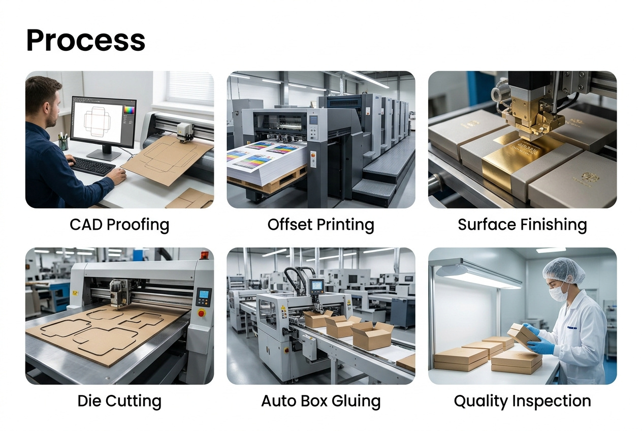
4. Critical Manufacturing Process Windows & Floor Controls
Now let us address shrinkage porosity through multi-stage real-time injection profiling and intensifier pressure control. A modern die-casting shot cycle is divided into three distinct hydraulic phases: - Phase 1 (Slow Approach): The piston advances smoothly at 0.15 to 0.30 m/s to accumulate molten metal ahead of the plunger tip without creating turbulent air-trapping waves in the shot sleeve. - Phase 2 (Fast Cavity Filling): As metal reaches the gate, the machine accelerates to high velocity (3.5 to 6.5 m/s) in less than 15 milliseconds, atomizing metal into the cavity through runner gates designed with hyperbolic tangent transitions. Cavity fill time is held strictly between 20 and 45 milliseconds to prevent pre-solidification skin formation. - Phase 3 (Intensification & Squeeze): The instant the cavity is filled (pressure spike detected), the machine shifts instantaneously into intensification squeeze mode. An auxiliary nitrogen-hydraulic accumulator drives the piston under pressures up to 80 to 120 MPa (12,000 to 17,000 psi). This immense intensification pressure forces additional molten metal into the cooling casting, physically squeezing out dendritic shrinkage voids and feeding the volumetric contraction until the gate freezes solid. To maximize effectiveness, the rise time to peak intensification pressure must occur in less than 20 milliseconds.5. Advanced Tooling, Metrology & Quality Governance
Mold thermal equilibrium is the third pillar of zero-porosity casting. If die temperatures fluctuate erratically, thermal hot-spots develop, causing unpredictable localized shrinkage. We engineer all die-casting tooling with conformal cooling channels machined via 5-axis CNC and high-pressure oil temperature control units (Regloplas). - Die temperature is maintained continuously at 160°C to 200°C for Zamak 5, and 220°C to 260°C for aluminum ADC12. - Squeeze pins (hydraulic core pins) are strategically driven into heavy boss sections 1.5 seconds after cavity filling, exerting localized compaction pressures exceeding 200 MPa directly on thermal mass hot-spots to guarantee 100% solid density where critical fastener threads will be tapped.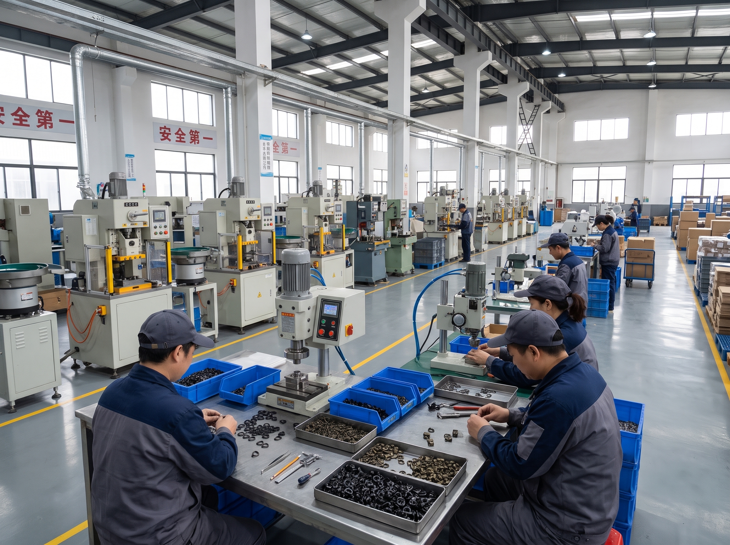
6. Statistical Process Capability & Defect Prevention
To verify internal casting integrity, non-destructive testing (NDT) is mandatory. We employ three complementary inspection modalities: First, automated helium mass spectrometer leak detection. Castings are clamped into automated sealing fixtures, evacuated, and pressurized with helium gas at 1.0 MPa. Leakage rates down to 10^-6 mbar*L/s are detected, ensuring absolute hermetic sealing for hydraulic and pneumatic applications. Second, real-time industrial X-ray inspection. Castings are scanned under 160 kV micro-focus X-ray tubes with automated defect recognition (ADR) algorithms that calculate porosity percentage according to ASTM E505 reference radiographs. Any casting exhibiting porosity exceeding Level 1 in critical sealing zones is automatically rejected. Third, Archimedes density testing. By measuring casting weight in air versus deionized water, bulk density is calculated: rho_actual = (W_air / (W_air - W_water)) * rho_water Zamak 5 castings must demonstrate a minimum density of 6.65 g/cm³ (99.2% of theoretical solid density).Shop-Floor Inspection SOP & Metrology Protocols
The following engineering standard operating procedure (SOP) is strictly enforced across all manufacturing cells handling this product class:
| Inspection Station | Critical Parameter | Testing Instrument | Sampling Frequency | Acceptance Criteria & Threshold |
|---|---|---|---|---|
| Molten Metal Chemistry | Alloy Composition & Purity | Optical Emission Spectrometer | Every furnace charge | Zamak 5 (Al: 3.8-4.2%, Cu: 0.7-1.1%, Mg: 0.03-0.06%, Pb <0.003%) |
| Vacuum Level Verification | Absolute Cavity Pressure | Digital Piezo Pressure Transducer | 100% of machine cycles | Cavity vacuum <50 mbar before metal enters gate |
| Shot Sleeve Velocity Profile | Phase 1, 2, 3 Velocity & Rise Time | Linear Optical Encoder + PLC | Continuous shot datalogging | Rise to intensification <20 ms; Intensification >90 MPa |
| Mold Thermal Regulation | Die Surface Temperature | Infrared Thermal Imaging + Oil TCU | Continuous closed-loop | Zamak 5: 180°C ± 10°C; ADC12: 240°C ± 15°C |
| Internal Density Audit | X-Ray Defect & Archimedes | 160kV X-Ray ADR + Density Test | 5 pcs / production hour | ASTM E505 Severity Level 1; Bulk density ≥ 6.65 g/cm³ |
Chief Engineer Floor Q&A: Solving Critical Sourcing Dilemmas
7. Thermal Stress Fatigue & Die Heat Checking Prevention
In high-pressure die-casting, the production cost of an individual zinc or aluminum component is heavily dominated by tooling depreciation. A hardened tool steel die cavity (typically machined from premium electroslag remelted Premium H13 or Dievar tool steel) is subjected to violent cyclic thermal shocks during every shot.
Consider the extreme thermodynamic conditions: Within 25 milliseconds, molten aluminum alloy at 680°C (or Zamak zinc at 430°C) is injected into the die cavity under pressures exceeding 80 MPa. The die surface temperature flashes upward by hundreds of degrees, inducing severe compressive thermal stresses. Less than two seconds later, the casting is ejected, and an automated robotic spray manifold douses the scorching die faces with a water-based lubricant emulsion, dropping the surface temperature down to 180°C within fractions of a second.
This cyclic thermal expansion and contraction induces severe low-cycle thermal fatigue, mathematically governed by the Coffin-Manson relation:
Where Delta epsilon_p is plastic strain amplitude per cycle, epsilon_f' is the fatigue ductility coefficient, N_f is cycles to crack initiation, and c is the fatigue exponent (-0.5 to -0.7).
Over tens of thousands of cycles, microscopic thermal fatigue cracks—known across the foundry industry as 'heat checking'—propagate across the die surface, creating an unsightly spiderweb pattern of raised fins on the finished casting. As these cracks deepen, molten metal infiltrates them, causing castings to stick during ejection and eventually leading to catastrophic gross die fracture.
To maximize die tooling lifespan past 250,000 shots on aluminum and over 1,000,000 shots on zinc, Apex Precision Hardware implements multi-stage surface engineered tooling protocols: First, after rough and finish CNC machining, die inserts undergo vacuum stress-relief tempering followed by plasma gas nitriding. Nitriding creates a hard, wear-resistant compound layer (depth 0.10 to 0.15 mm, surface hardness >1,000 HV) with high compressive residual stresses that delay heat-checking crack initiation. Second, we employ advanced additive manufacturing (metal 3D printing in maraging steel) to grow conformal internal cooling passages that curve three-dimensionally around complex core pins, keeping internal die surface temperature swings within a tight, non-destructive delta of less than 80°C throughout the continuous casting shift.
8. Helium Mass Spectrometry Leak Testing for Pressure Tightness
When high-pressure castings are deployed in critical fluid containment systems—such as industrial hydraulic door closer cylinders, automotive fuel pump housings, or subsea pneumatic latch bodies—conventional underwater bubble leak testing is utterly inadequate. A submerged visual bubble test can only detect gross leaks on the order of 10^-3 to 10^-4 mbar*L/s, which allows micro-fine hydraulic fluid or pressurized refrigerant gases to slowly weep through porous grain boundaries over months of field service.
Our quality assurance laboratory guarantees hermetic casting integrity using automated Helium Mass Spectrometry Vacuum Chamber Testing (ASTM E499 / ISO 20485).
The casting is placed inside a stainless steel vacuum test chamber, clamped with automated pneumatic silicone seals, and evacuated to high vacuum (<1 mbar). Simultaneously, high-purity helium gas (which possesses a tiny atomic diameter of only 0.26 nanometers, smaller than any liquid or air molecule) is injected into the internal core of the casting at 1.0 to 1.5 MPa. If a microscopic through-wall shrinkage channel or interconnected porosity flaw exists, helium atoms leak into the surrounding vacuum chamber and are instantly drawn into the flight tube of a magnetic sector mass spectrometer.
The system achieves an analytical sensitivity capable of detecting leak rates down to 1 x 10^-8 mbar*L/s—equivalent to losing less than one drop of hydraulic oil every thirty years! Every casting certified through this station receives an individual serialized barcode recording the precise measured leak rate, giving our overseas OEM clients absolute confidence in mission-critical hydraulic assemblies.
Conclusion: Practical Engineering Takeaways for Sourcing Directors
Porosity in die-castings is not an inevitable fact of life; it is an engineering flaw born of poor runner design, inadequate vacuum evacuation, and weak intensification control. When sourcing high-integrity industrial hardware and pressure-tight enclosures, partner with a manufacturing foundry that commands computer-simulated mold flow, active vacuum evacuation (<50 mbar), and automated X-ray NDT inspection.Extended Metallurgical Analysis & Failure Prevention Standards
In our eighteen years of precision manufacturing leadership at Apex Precision Hardware, we have repeatedly proven that mechanical failures are never random acts of chance. Every sheared bolt, every delaminated surface coating, every cracked stamping leaf, and every seized hydraulic pivot tells a precise atomic story of localized stress concentrations, unaddressed microstructural inclusions, or flawed thermal processing. When an overseas original equipment manufacturer partners with our facility, they are not merely purchasing thousands of metal parts; they are licensing an entire ecosystem of manufacturing rigor and thermodynamic discipline.
From the initial chemical spectroscopic verification of raw bar stock (confirming tight bounds on sulfur, phosphorus, and residual interstitial elements) to the continuous monitoring of cutting fluid concentrations and spindle vibration spectra, our shop-floor engineering team maintains absolute ownership over the variables that dictate product longevity. By enforcing rigorous Production Part Approval Process (PPAP Level 3) protocols, including comprehensive Gage R&R measurement system studies that restrict total gauge error to less than eight percent of overall tolerance bands, we ensure that every critical specification approved on the pilot blueprint is replicated with sub-micron repeatability across production runs exceeding hundreds of thousands of units.
Furthermore, our global logistics protocols reflect the same uncompromising engineering mindset. Finished precision hardware is thoroughly degreased in multi-stage ultrasonic baths, treated with non-oily volatile corrosion inhibitor (VCI) molecular barriers, vacuum sealed in airtight nitrogen-flushed barrier bags, and packed into custom-molded heavy-duty export containers equipped with calcium chloride desiccant strips. This rigorous defense-in-depth packaging strategy guarantees that when our shipments cross equatorial ocean trade routes, they arrive at your assembly facilities in Stuttgart, Detroit, Yokohama, or Gothenburg in pristine, laboratory-clean condition, ready for instantaneous automated integration.