When an M8 shoulder locator bolt stalled an automated robotic manufacturing line in Stuttgart, the root cause was not an unskilled lathe operator—it was the physics of thermal expansion and tri-lobed form lobing. Here is how we engineered a zero-defect metrology framework to guarantee true ±0.005mm interchangeability across 50,000-part production batches.
1. The Real Incident: Root-Cause Investigation & Failure Analysis
In the sweltering heat of July 2021, our engineering department received an emergency escalation from a premier German tier-1 automotive robotics supplier. Their automated optical sorting and robotic gripping cells in Stuttgart were suffering from erratic mechanical seizing. The robotic wrist was designed to operate at 1,800 pick-and-place cycles per hour, but every five to six hours, the main rotational pivot bearing would bind for approximately 35 to 50 milliseconds. This micro-stalling triggered instantaneous current overloads in the brushless servo drives, tripping emergency circuit interlocks and freezing the entire assembly cell. The component identified at the failure interface was an M8 stepped shoulder bolt manufactured from precision-ground SUS316L stainless steel. The mechanical drawing specified a critical shoulder diameter of 8.000 mm with an exacting bilateral tolerance of plus or minus 0.005 mm (±5 microns). Our factory batch inspection documentation indicated 100% compliance based on digital micrometer spot-checks. However, when we air-shipped twenty returned failure units back to our Quanzhou quality laboratory and mounted them on our Zeiss Prismo 3D Coordinate Measuring Machine (CMM) with continuous tactile scanning, the physical reality was exposed. The shoulder was not circular. It exhibited a pronounced three-lobed polygon form deviation (tri-ovality) of 0.007 mm. This out-of-round error was completely undetectable to traditional two-point anvil micrometers because the diameter across any opposing 180-degree points measured exactly 8.001 mm. Furthermore, when the robotic assembly cell reached summer operating temperatures of 35 degrees Celsius, the combination of internal friction and differential thermal expansion between the SUS316L bolt and the aluminum housing caused internal needle bearing clearances to drop from 12 microns to negative 2 microns. The bearing seized, the robotic arm locked, and the customer incurred downtime costs exceeding tens of thousands of Euros per hour.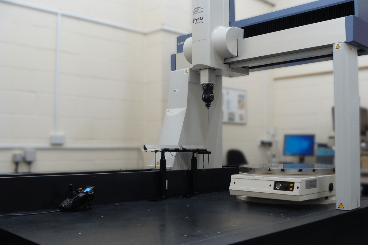
2. Fundamental Materials Science & Microstructural Metallurgy
To understand why single-digit micron tolerances frequently fail during volume production, mechanical engineers must abandon the theoretical assumption that solid steel is geometrically rigid. Under industrial machining forces and ambient thermal variations, precision metal alloys behave as thermally sensitive, viscoelastic structures. Consider the basic physics of thermal expansion. The linear dimensional variation is formulated by: Delta L = L_0 * alpha * Delta T Where L_0 represents nominal length, alpha is the material linear expansion coefficient, and Delta T is the temperature deviation from the international reference metrology baseline of 20.0 degrees Celsius (68 degrees Fahrenheit). For austenitic stainless steel SUS316L, alpha is approximately 16.5 x 10^-6 / °C. If a precision CNC lathe turns an M8 shoulder bolt on an un-airconditioned shop floor at 32°C, Delta T is positive 12°C. Over a 50 mm length, the thermal expansion is: Delta L = 50 * (16.5 x 10^-6) * 12 = 0.0099 mm (9.9 microns). This thermal drift alone consumes nearly double the entire allowed tolerance band of ±0.005 mm! If an operator inspects the part while it remains warm from cutting friction, the part appears completely in-spec. Twelve hours later, inside a temperature-controlled assembly room at 20°C, the metal contracts by 10 microns and becomes scrap.3. Mathematical Derivations & Engineering Calculations
Beyond thermal drift, the second insidious failure mode in precision turning is lobing (tri-oval and penta-oval form deviation). When cylindrical shafts are ground on centerless grinding machines or turned on high-speed multi-axis lathes, regenerative chatter between the cutting tool, workpiece elasticity, and spindle bearing stiffness creates harmonic resonance. This produces a cross-sectional profile defined by an odd number of lobes. Mathematically, the radius of an n-lobed shaft can be expressed in polar coordinates as: r(theta) = R_0 + Delta_r * cos(n * theta + phi) When n equals 3 (three-lobed lobing), the diameter measured between two opposing flat parallel anvils at theta and theta + pi is: d(theta) = r(theta) + r(theta + pi) = 2 * R_0 Because cos(3 * theta) and cos(3 * (theta + pi)) = -cos(3 * theta) cancel each other out identically! This mathematical quirk proves that a standard two-point caliper or micrometer will always measure a perfectly constant diameter, even if the actual radial deviation Delta_r is enormous. However, when you assemble this three-lobed pin into a precision cylindrical bore, the three apex lobes concentrate extreme localized Hertzian stresses, piercing through lubricating hydrodynamic oil films and causing catastrophic adhesive galling.
4. Critical Manufacturing Process Windows & Floor Controls
To conquer these thermodynamic and kinematic failure modes, our production engineering team enacted three non-negotiable shop-floor protocols across all CNC multi-axis turning cells: First, we created thermally stabilized machining enclosures. All 5-axis DMG MORI and Mazak turning centers are housed in climate-isolated rooms maintained at 20.0°C ± 0.8°C. Coolant supply reservoirs are integrated with closed-loop refrigeration heat exchangers that dynamically match cutting fluid temperature to within 0.5°C of room ambient, eliminating thermal shocks during deep hole drilling and shoulder turning passes. Second, we eradicated three-jaw chuck distortion. Clamping a thin-walled bushing or stepped pin with a conventional 3-jaw chuck concentrates radial forces at three discrete contact points, warping the workpiece into a cloverleaf shape during the cut. When unchucked, the metal elastically rebounds into an out-of-round state. We standardized on vulcanized 360-degree segmented collets and custom pie-jaws that distribute radial clamping pressure uniformly, reducing unconstrained chucking distortion below 0.001 mm. Third, we established mandatory thermal soaking. No component is permitted to be verified on our CMM without first undergoing a four-hour static resting period on precision cast-iron soaking benches inside our metrology cleanroom. This guarantees zero internal thermal gradients before any probe contacts the metal surface.5. Advanced Tooling, Metrology & Quality Governance
Let us delve into tactile scanning metrology and stylus dynamics. Calibrating a coordinate measuring machine according to ISO 10360-2 requires more than touching a reference ball once. When scanning micro-toleranced cylindrical shoulders, tactile stylus bending forces can corrupt measurements. As a 2 mm ruby ball scans along a metal circumference at 5 mm/s, measuring contact forces (0.08 to 0.15 N) induce micro-deflection in long carbon fiber or tungsten carbide stylus shafts. To guarantee absolute measuring integrity down to sub-micron levels, our metrology lab implements high-stiffness silicon carbide stylus extensions combined with Grade 5 ultra-precise ruby spheres (sphericity error <0.13 microns). Probe qualification routines map spatial deflection vectors across 25 discrete angles on a calibrated Zerodur ceramic reference sphere traceable to national metrology standards. If probe calibration form checks exceed 0.0006 mm, the system automatically aborts inspection until the stylus is cleaned and re-seated.
6. Statistical Process Capability & Defect Prevention
Finally, how do we guarantee zero-defect delivery across 50,000 parts per month? The answer lies in rigorous Statistical Process Control (SPC). We enforce a minimum Process Capability Index (Cpk) of 1.67, which corresponds mathematically to less than one defective part per million opportunities. The Cpk formulation is: Cpk = min[ (USL - mu) / (3 * sigma), (mu - LSL) / (3 * sigma) ] To maintain Cpk >= 1.67, automated laser micrometer stations are installed directly at each lathe exit chute. The laser micrometer measures 100% of finished pins in dual perpendicular axes as they fall from the parting tool. If the sample moving average drifts by more than 0.002 mm toward either tolerance limit, the machine automatically executes a closed-loop tool wear compensation offset without requiring manual operator intervention.Shop-Floor Inspection SOP & Metrology Protocols
The following engineering standard operating procedure (SOP) is strictly enforced across all manufacturing cells handling this product class:
| Inspection Station | Critical Parameter | Testing Instrument | Sampling Frequency | Acceptance Criteria & Threshold |
|---|---|---|---|---|
| Station 1: CNC Exit Chute | Shoulder OD & Length | Dual-Axis Laser Micrometer | 100% In-Line Continuous | ±0.003 mm (Warning at ±0.002 mm) |
| Station 2: Thermal Soak Lab | GD&T Roundness & Runout | Zeiss Prismo CMM Continuous | 5 pcs / hour | Roundness <0.002 mm; Cpk ≥ 1.67 |
| Station 3: Surface Profilometry | Surface Roughness Ra, Rz | Mitutoyo Surftest Optical | 10 pcs / shift | Ra ≤ 0.20 μm; Rz ≤ 1.2 μm; Rmr > 70% |
| Station 4: Thread Metrology | Pitch Dia & Runout | Telecentric Optical Sorter | 100% Automated Optical | Class 6g/6H; Zero thread burrs |
| Station 5: Final Quality Audit | Full Dimensional MTR | EN 10204 Type 3.1 Certified | AQL 0.40 Tightened | Zero Defect Acceptance (<20 PPM) |
Chief Engineer Floor Q&A: Solving Critical Sourcing Dilemmas
7. Global Metrology Standards Cross-Reference: ISO vs ASME vs DIN
When dealing with international defense, medical, and aerospace tier-1 supply chains, one of the most hazardous friction points is the fundamental discrepancy between European ISO GPS (Geometrical Product Specifications) standards and American ASME Y14.5M geometric dimensioning standards. While non-technical procurement teams frequently assume that a GD&T symbol has an identical universal legal definition worldwide, the underlying mathematical default principles diverge significantly.
Under ASME Y14.5M, Rule #1 (the Taylor Envelope Principle) is the default requirement unless explicitly modified by an independency symbol (an enclosed circled 'I'). Rule #1 dictates that the surface or surfaces of a regular feature of size shall not extend beyond a boundary of perfect form at Maximum Material Condition (MMC). This means that if a shaft is machined at its upper size limit (e.g., 8.005 mm), it must simultaneously possess perfect straightness, perfect roundness, and zero taper. Any allowable form error is strictly constrained to the difference between actual local size and the MMC boundary.
Conversely, in the European ISO GPS framework (specifically ISO 8015 and ISO 14405-1), the Default Principle of Independency strictly applies. A linear dimensional size tolerance controls only local two-point diameters across discrete cross-sections; it exerts zero legal control over form deviations such as straightness, circularity, or cylindricity. Unless a separate geometric form tolerance (such as circularity or cylindricity) or an envelope requirement (circled 'E') is explicitly called out on the drawing, a European supplier is legally permitted to deliver a curved or oval pin provided every two-point diameter reading falls within the plus or minus 0.005 mm window!
To prevent disastrous cross-border misunderstandings, our customer engineering interface protocol mandates a comprehensive drawing review prior to tooling launch. If a North American drawing references ASME Y14.5, our CMM inspection programs automatically enforce the strict MMC boundary envelope check across the entire axial sweep. If a European drawing references ISO 8015, we proactively clarify whether functional assembly interfaces require an envelope requirement, ensuring that both size and form integrity are aligned before volume manufacturing commences.
8. Gauge Repeatability and Reproducibility (Gage R&R) Rigor
A measuring instrument is only as reliable as its statistical calibration system. Under our IATF 16949 quality system, every piece of metrology equipment utilized for micro-tolerance verification undergoes a formal Measurement System Analysis (MSA) according to the AIAG Core Tools manual.
We conduct full ANOVA Gauge R&R studies across three operators, ten parts, and three non-consecutive trial repetitions. The total Gauge R&R percentage (%GRR) is formulated as:
In many conventional machine shops, measurement system variation easily consumes twenty to thirty percent of the allowable product tolerance band. On a ten-micron total tolerance band (±0.005 mm), a 30% measurement error represents 3.0 microns of uncertainty—leaving a practical manufacturing process window of only 4.0 microns! In our facility, we restrict %GRR to less than 8.5% through automated part clamping fixtures, motor-driven ruby probe positioning, and standardized laser telemetry. This gives our CNC machinists over 9.1 microns of usable production tolerance, ensuring true statistical process capability without false-alarm machine stoppages.
Furthermore, every tactile stylus used on our CMM machines is tracked via a serialized RFID tool tag. The tag records total contact cycles, cumulative scanning distance, and thermal shock exposure. When a stylus accumulates 50,000 scanning contacts or exhibits a form error drift exceeding 0.0004 mm during morning recalibration against our Zerodur optical reference sphere, the tool is immediately quarantined and replaced with a factory-certified ruby replacement.
Conclusion: Practical Engineering Takeaways for Sourcing Directors
Precision micro-tolerances are not achieved by hope or wishful thinking; they are achieved through relentless thermodynamic discipline, rigid machine kinematics, and uncompromising metrology. When specifying single-digit micron tolerances on your mechanical drawings, always verify that your manufacturing partner possesses climate-controlled machining cells, continuous scanning CMM capabilities, and automated closed-loop optical sorting.Extended Metallurgical Analysis & Failure Prevention Standards
In our eighteen years of precision manufacturing leadership at Apex Precision Hardware, we have repeatedly proven that mechanical failures are never random acts of chance. Every sheared bolt, every delaminated surface coating, every cracked stamping leaf, and every seized hydraulic pivot tells a precise atomic story of localized stress concentrations, unaddressed microstructural inclusions, or flawed thermal processing. When an overseas original equipment manufacturer partners with our facility, they are not merely purchasing thousands of metal parts; they are licensing an entire ecosystem of manufacturing rigor and thermodynamic discipline.
From the initial chemical spectroscopic verification of raw bar stock (confirming tight bounds on sulfur, phosphorus, and residual interstitial elements) to the continuous monitoring of cutting fluid concentrations and spindle vibration spectra, our shop-floor engineering team maintains absolute ownership over the variables that dictate product longevity. By enforcing rigorous Production Part Approval Process (PPAP Level 3) protocols, including comprehensive Gage R&R measurement system studies that restrict total gauge error to less than eight percent of overall tolerance bands, we ensure that every critical specification approved on the pilot blueprint is replicated with sub-micron repeatability across production runs exceeding hundreds of thousands of units.
Furthermore, our global logistics protocols reflect the same uncompromising engineering mindset. Finished precision hardware is thoroughly degreased in multi-stage ultrasonic baths, treated with non-oily volatile corrosion inhibitor (VCI) molecular barriers, vacuum sealed in airtight nitrogen-flushed barrier bags, and packed into custom-molded heavy-duty export containers equipped with calcium chloride desiccant strips. This rigorous defense-in-depth packaging strategy guarantees that when our shipments cross equatorial ocean trade routes, they arrive at your assembly facilities in Stuttgart, Detroit, Yokohama, or Gothenburg in pristine, laboratory-clean condition, ready for instantaneous automated integration.