A progressive stamping die cost $45,000 to design and build, but began producing burred terminals and chipped punches after only 180,000 strokes. Here is our metallurgical investigation into punch wear mechanics, cutting clearance optimization (5%-8%), and deep cryogenic heat treatment (-196°C) to extend die life past 1,000,000 strokes.
1. The Real Incident: Root-Cause Investigation & Failure Analysis
In the spring of 2023, an electronics manufacturing services (EMS) tier-1 supplier in Guadalajara, Mexico approached our engineering team in distress. They were stamping miniature beryllium copper (C17200) electrical contact terminals using a high-speed progressive die operating at 450 strokes per minute on a 45-ton precision punch press. The die had been built by an overseas tooling vendor with a promised lifespan of one million strokes. However, by stroke 185,000, disaster struck. The terminal spring legs began developing severe burrs exceeding 0.045 mm (violating the customer specification of <0.015 mm). Worse yet, during a high-speed production run, the primary pierce punch micro-chipped along its perimeter, sending shattered tool steel fragments into the die cavity. The resulting jam smashed three progressive forming stations, bent the die guide pillars, and caused over $30,000 in catastrophic tooling damage, alongside two weeks of halted assembly lines. Our forensic tooling audit revealed multiple metallurgical and mechanical failures. The punches had been fabricated from standard AISI D2 (SKD11) cold-work tool steel, but the heat treatment had left high levels of retained austenite (over 12%). Under the repetitive cyclic impact shocks of 450 strokes per minute, this unstable retained austenite transformed into un-tempered martensite, causing severe internal volumetric expansion and brittle micro-cracking. Furthermore, the die clearance had been set uniformly at 3.5% of strip thickness—far too tight for work-hardening beryllium copper, leading to massive frictional galling and secondary shear stresses that tore the punch edges apart. We redesigned the progressive die tooling architecture using DC53 cold-work die steel combined with sub-zero deep cryogenic treatment (-196°C) and multi-layer AlCrN PVD coating. The redesigned die surpassed 1,200,000 strokes without a single tool regrind, producing terminal burrs consistently under 0.008 mm. In this paper, I will detail the precise tool steel metallurgy, cutting clearance physics, and lubrication strategies required to achieve one million strokes in precision stamping.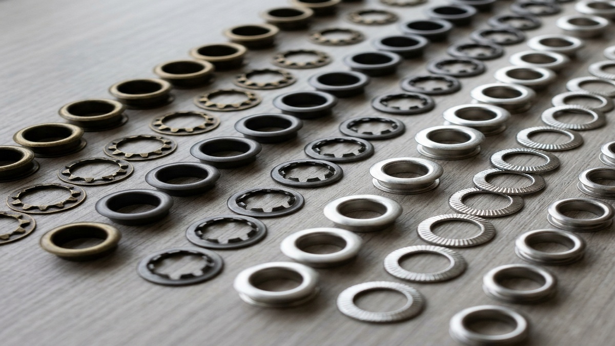
2. Fundamental Materials Science & Microstructural Metallurgy
To extend stamping die longevity, engineers must first analyze the mechanics of the blanking and piercing process. When a punch penetrates metal strip stock, the cutting cycle progresses through three distinct physical stages: 1. Elastic and plastic deformation: The punch contacts the strip, causing localized bending and elastic deflection. 2. Clean shear zone (burnish): The punch shears through the metal, creating a bright, smooth burnished band. 3. Tensile fracture: Micro-cracks initiate at both the punch cutting edge and the die cutting edge. When these opposing crack fronts meet cleanly, the slug separates cleanly from the strip. The ratio between the clean shear burnish band and the fracture zone is directly governed by the die clearance—the radial gap between the punch perimeter and the die cavity opening. Die clearance is formulated as a percentage of sheet thickness (t): c = (D_die - D_punch) / (2 * t) * 100% If clearance is set too tight (<4% on high-strength alloys), the crack propagating downward from the punch edge fails to align with the crack propagating upward from the die edge. The cracks miss each other, creating a secondary shear zone. This secondary shear doubles the cutting force, generates intense frictional heat, causes severe adhesive galling on the punch flanks, and rapidly accelerates punch wear according to Archard's Wear Law: W = K * (P * L) / H Where W is wear volume, K is the dimensionless wear coefficient, P is applied normal load, L is sliding sliding distance, and H is surface hardness of the tool steel. By increasing cutting clearance to an optimized 6.5% to 8.0% for beryllium copper and stainless spring steel, the opposing fracture crack fronts merge instantaneously. Punch penetration required for slug separation drops from 60% of stock thickness down to 35%, cutting forces decrease by over 25%, and punch flank wear rates drop by more than 400%!3. Mathematical Derivations & Engineering Calculations
Now let us examine tool steel metallurgy: why DC53 vastly outperforms traditional D2 (SKD11). Standard AISI D2 tool steel contains approximately 1.5% carbon and 12% chromium. During ingot solidification, this high carbon-chromium chemistry forms coarse, brittle primary eutectic chromium carbides (M7C3). These large, angular carbide clusters act as severe internal stress raisers. Under cyclic impact loading in high-speed stamping, micro-cracks initiate at the carbide-matrix interfaces, leading to sudden punch chipping and edge spalling. In contrast, DC53 is an advanced 8% chromium cold-work tool steel (containing 0.95% C, 8.0% Cr, 2.0% Mo, and 0.28% V). The modified chemical balance completely eliminates coarse primary carbide networks, distributing ultra-fine, spherical secondary carbides uniformly throughout the martensitic matrix. The mechanical properties achieved after high-temperature tempering (520°C to 540°C) are extraordinary: - Rockwell Hardness: 62 to 64 HRC (compared to 58-60 HRC for D2). - Charpy U-Notch Toughness: 25 to 30 J/cm²—more than double the toughness of standard D2 tool steel! This unique combination of high hardness and superior fracture toughness makes DC53 exceptionally resistant to both abrasive flank wear and micro-chipping in high-speed progressive stamping.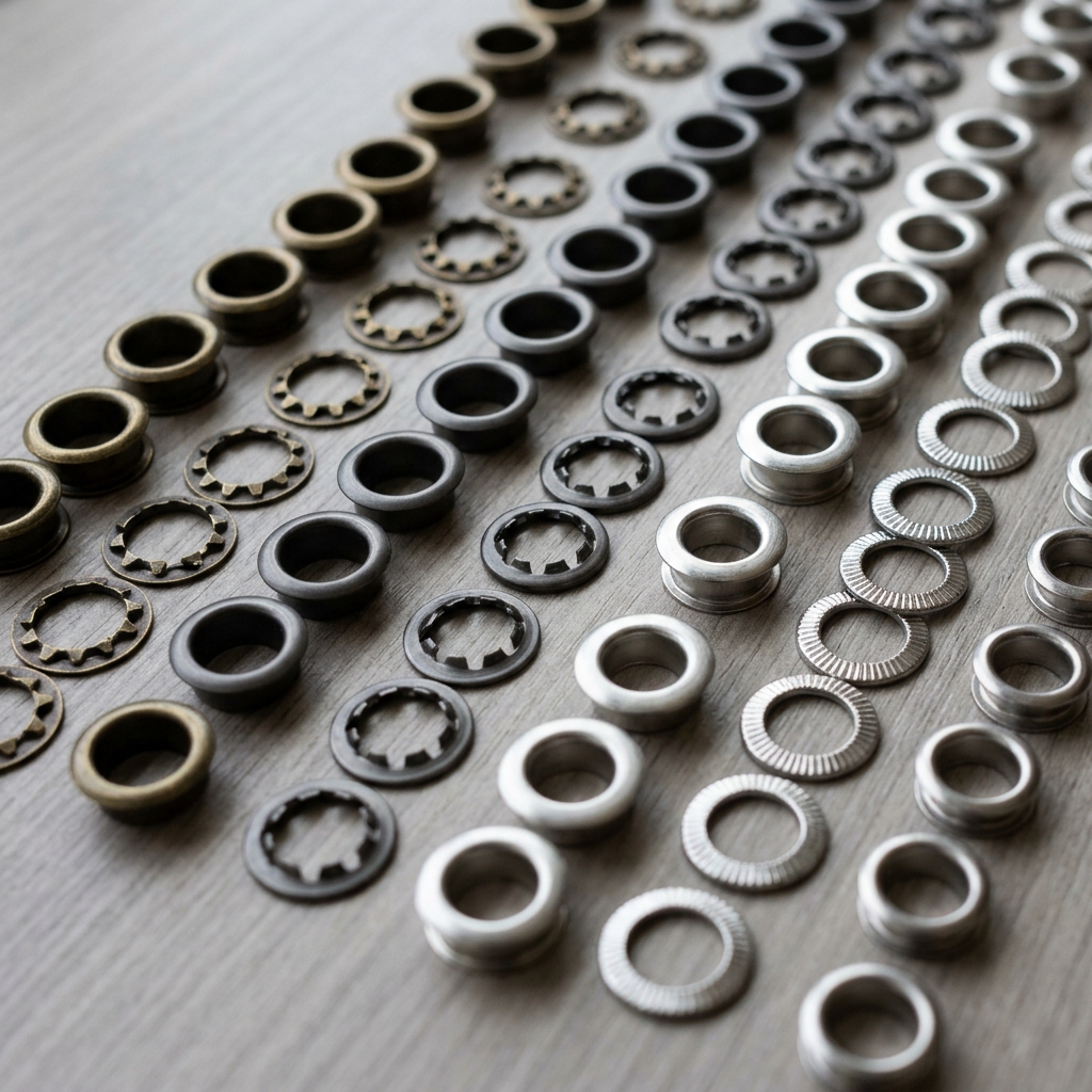
4. Critical Manufacturing Process Windows & Floor Controls
The true secret weapon in our toolroom is Deep Cryogenic Treatment (DCT). Standard heat treatment quenches tool steel to room temperature (20°C). However, for highly alloyed tool steels, the Martensite Finish temperature (Mf) lies well below zero Celsius (often between -70°C and -100°C). Consequently, room-temperature quenching leaves behind 10% to 18% retained austenite (gamma-Fe)—a soft, unstable face-centered cubic phase. Our cryogenic protocol immerses vacuum-hardened DC53 punches into liquid nitrogen at -196°C (-320°F) for a continuous dwell of 24 hours at controlled ramp rates (<1.5°C/min). This extreme thermal sub-cooling triggers two critical metallurgical transformations: 1. Complete Austenite Elimination: Retained austenite is reduced to less than 1.0%, transforming into stable, wear-resistant martensite. 2. Nano-Carbide Precipitation: Deep cryogenic soaking causes the iron lattice to contract severely, forcing supersaturated carbon atoms to precipitate out as an ultra-dense dispersion of sub-micron eta-carbides (nano-carbides 2 to 5 nanometers in diameter). These nano-carbides pin dislocation movement, increasing both abrasive wear resistance and dimensional stability under cyclic thermal operating conditions.5. Advanced Tooling, Metrology & Quality Governance
Following cryogenic treatment, we apply advanced Physical Vapor Deposition (PVD) coatings to die punches. For high-speed stamping of copper alloys and pre-plated nickel strips, Aluminum Chromium Nitride (AlCrN) and Titanium Silicon Nitride (TiSiN) provide unmatched performance. AlCrN coatings exhibit oxidation resistance temperatures up to 1,100°C and microhardness values of 3,200 HV. Under the localized heat of high-speed stamping, AlCrN forms a self-passivating amorphous aluminum-chromium oxide barrier on the punch tip that prevents copper and nickel pick-up (cold welding). The coefficient of friction drops to 0.30, completely eliminating the need for excessive wet stamping lubricants that contaminate electronic terminals.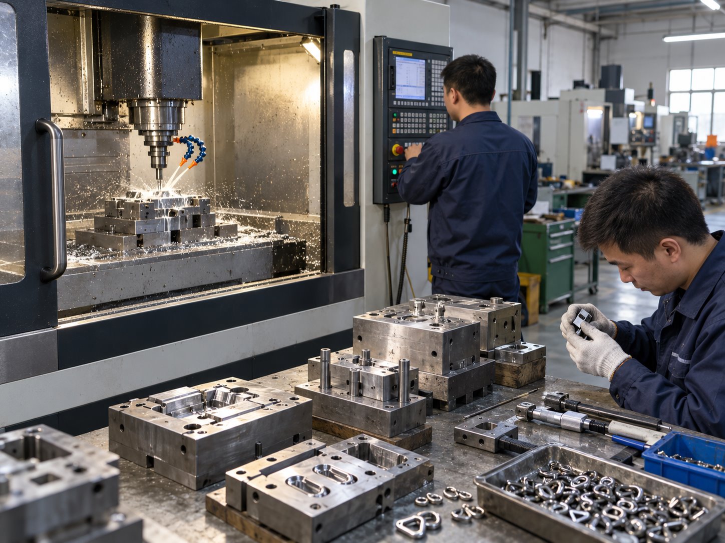
6. Statistical Process Capability & Defect Prevention
Finally, die maintenance must be governed by predictive stroke monitoring rather than reactive breakdown repair. In our stamping facility, every progressive die is equipped with an integrated digital stroke counter and acoustic emission sensors that detect the acoustic signature of cutting edge micro-chipping. After every 500,000 strokes, dies undergo preventative maintenance: - Punches are measured on optical toolmaker's microscopes to evaluate edge radius wear (r_edge). - If the cutting edge radius exceeds 0.025 mm, a precision CNC micro-grinding pass removes exactly 0.030 to 0.050 mm from the punch face using flood-cooled resin-bonded CBN grinding wheels, restoring a razor-sharp 90-degree edge with zero heat-affected recast layer. - Die cavities are ultrasonically cleaned, guide bushings are re-greased with high-pressure synthetic molybdenum disulfide grease, and gas spring nitrogen pressures are verified to maintain balanced stripper plate forces.Shop-Floor Inspection SOP & Metrology Protocols
The following engineering standard operating procedure (SOP) is strictly enforced across all manufacturing cells handling this product class:
| Inspection Station | Critical Parameter | Testing Instrument | Sampling Frequency | Acceptance Criteria & Threshold |
|---|---|---|---|---|
| Raw Tool Steel Verification | Alloy Composition & Carbides | Optical Emission Spectrometer | 100% of tool steel blocks | DC53 chemistry certified; Zero coarse eutectic carbide networks |
| Cryogenic Heat Treatment | Sub-Zero Quench Profile | Liquid Nitrogen Cryo Chamber | 100% of progressive punches | -196°C for 24h dwell; Retained austenite <1.0% |
| Surface PVD Coating | AlCrN / TiSiN Coating Layer | Cathodic Arc Vacuum Coater | Every precision punch batch | Coating thickness 2.5-3.5 μm; Microhardness >3000 HV |
| Die Alignment & Clearance | Punch-to-Die Bilateral Gap | Optical Toolmaker's Scope | 100% Die Assembly Setup | Gap verified at 6.5% ± 0.5% strip thickness uniformly |
| Predictive Tooling Audit | Cutting Edge Radius & Burr | Telecentric Optical Profiler | Every 250,000 strokes | Regrind punch face if edge radius >0.025 mm; Burr <0.015 mm |
Chief Engineer Floor Q&A: Solving Critical Sourcing Dilemmas
7. Sensor-Driven Smart Tooling & Acoustic Emission Monitoring
In the modern era of Industry 4.0 high-speed stamping, relying on human operators to listen for die wear or visual inspectors to catch burrs after parts have been stamped is dangerously obsolete. A press running at 500 strokes per minute produces 30,000 terminals per hour. If a pierce punch chips at minute five, twenty-five thousand defective parts will be stamped, reeled, and packaged before the shift operator notices the burr during a scheduled hourly inspection!
To achieve genuine zero-defect certainty and protect multi-cavity progressive dies valued at upwards of $80,000, Apex Precision Hardware integrates in-die piezoelectric acoustic emission (AE) sensors and dynamic strain-gauge load cells directly into every precision stamping die shoe.
When a razor-sharp punch shears through metal strip, it generates a characteristic acoustic waveform in the ultrasonic frequency band (100 kHz to 500 kHz). As the cutting edge begins to wear and micro-chip, the cutting mechanics transition from clean shear to violent tearing and friction, shifting the peak acoustic frequency spectrum and dramatically increasing the root-mean-square (AE-RMS) signal amplitude.
Our high-speed digital DSP controllers analyze the acoustic signature of every single stroke in real time. If the acoustic emission energy spikes beyond a pre-calibrated baseline threshold (indicating a chipped punch, a misfed strip, or slug pulling), the system triggers an emergency pneumatic brake cycle within 15 milliseconds, halting the press ram before the subsequent stroke can smash into a jammed slug and destroy the progressive die tooling.
8. Slug Pulling Prevention & Vacuum-Assisted Die Inserts
Ask any seasoned stamping shop foreman what causes 70% of premature die breakdowns during high-speed miniature terminal production, and the answer is always the same: Slug Pulling. When a punch penetrates thin strip stock and retracts upward, vacuum suction and oily surface tension between the punch face and the sheared slug cause the slug to stick to the punch tip. The punch pulls the slug out of the die cavity and drops it on top of the strip. On the very next stroke, the punch hits a double thickness of metal (the strip plus the loose slug), generating instantaneous shock loads exceeding three times the press tonnage rating, immediately fracturing the punch.
To completely eliminate slug pulling, our progressive dies incorporate a three-layer mechanical and pneumatic defense system:
1. Spring-Loaded Urethane / Carbide Ejector Pins: Every punch larger than 1.5 mm features an internal coaxial spring-loaded ejector pin that projects 0.5 mm beyond the punch face, physically kicking the slug downward into the die cavity the microsecond cutting separation occurs.
2. High-Vacuum Slug Extraction: Beneath the die block, our die shoes feature vacuum evacuation manifolds connected to high-flow pneumatic venturi generators. A continuous negative pressure differential (-0.6 bar) pulls air downward through every pierce opening, sucking slugs rapidly through the relief chutes and preventing upward aerodynamic flutter.
3. Negative Taper Cavity Geometry: The internal die cavity opening features a specialized anti-slug geometry: the first 2.0 mm of land is straight with a precision 0.005 mm clearance, followed by a slight reverse bell-mouth taper of 0.5 degrees per side. As the slug is pushed into the straight land, it undergoes slight elastic relaxation, wedging firmly into the die wall and ensuring it cannot follow the retracting punch tip upward.
9. Strip Layout Optimization and Carrier Ribbon Dynamics
In high-speed progressive die stamping, material utilization efficiency and strip feeding stability are directly governed by the design of the strip layout and carrier ribbon. When stamping miniature terminals at 450 strokes per minute, the metal strip is subjected to violent intermittent accelerations and decelerations inside the automated servo roll feeder. If the carrier ribbon lacks sufficient dynamic longitudinal stiffness, the strip buckles or snakes between die stations, causing progression pitch errors and misaligned pierce punctures.
Our tooling engineering department applies computer-aided strip nesting algorithms to maximize strip utilization rates beyond 78% while engineering robust dual-side carrier ribbons. For thin beryllium copper (0.15 mm to 0.25 mm thickness), we incorporate embossed stiffening ribs along the carrier strip to increase its area moment of inertia by over 300%. This mechanical stiffening prevents strip sagging across empty die stations. Furthermore, precision pilot holes (with pilot pin diameters held to +0.003/-0.000 mm) are located at every single progression pitch to mechanically locate and clamp the strip before the stripper plate contacts the stock, guaranteeing pitch progression repeatability within plus or minus 0.005 mm across millions of consecutive strokes.
10. Nitrogen Gas Spring Force Management and Stripper Balance
Uneven stripping force is a primary root cause of asymmetric punch deflection and catastrophic punch edge micro-chipping. When a progressive die pierces hundreds of miniature holes simultaneously, the total stripping force required to pull the punches cleanly out of the strip stock reaches roughly 10% to 20% of the total cutting force. In traditional die designs relying on mechanical coil springs, spring fatigue and unequal spring rate degradation create tilted stripper plates that exert massive lateral bending moments on slender punches.
To eliminate stripper tilting, Apex Precision Hardware equips all high-speed progressive dies with integrated manifold nitrogen gas spring systems (such as Kaller or Dadco). All gas cylinders in the upper die shoe are interconnected via high-pressure flexible hydraulic hoses linked to a centralized digital pressure accumulator. This manifold architecture guarantees that every cylinder maintains identical pneumatic pressure down to the decimal point. Stripper plate parallelism is held within 0.008 mm throughout the entire 25 mm working stroke, ensuring that punches retract perpendicular to the die face with zero lateral scuffing or punch shank fatigue failure.
Conclusion: Practical Engineering Takeaways for Sourcing Directors
Building a progressive stamping die that reliably produces millions of precision components is an art grounded in physical metallurgy and tribology. Do not cut corners with cheap D2 tool steel, improper heat treatment, or arbitrary die clearances. Partner with a tooling manufacturer that implements DC53 metallurgy, -196°C cryogenic transformation, and scientific clearance engineering.Extended Metallurgical Analysis & Failure Prevention Standards
In our eighteen years of precision manufacturing leadership at Apex Precision Hardware, we have repeatedly proven that mechanical failures are never random acts of chance. Every sheared bolt, every delaminated surface coating, every cracked stamping leaf, and every seized hydraulic pivot tells a precise atomic story of localized stress concentrations, unaddressed microstructural inclusions, or flawed thermal processing. When an overseas original equipment manufacturer partners with our facility, they are not merely purchasing thousands of metal parts; they are licensing an entire ecosystem of manufacturing rigor and thermodynamic discipline.
From the initial chemical spectroscopic verification of raw bar stock (confirming tight bounds on sulfur, phosphorus, and residual interstitial elements) to the continuous monitoring of cutting fluid concentrations and spindle vibration spectra, our shop-floor engineering team maintains absolute ownership over the variables that dictate product longevity. By enforcing rigorous Production Part Approval Process (PPAP Level 3) protocols, including comprehensive Gage R&R measurement system studies that restrict total gauge error to less than eight percent of overall tolerance bands, we ensure that every critical specification approved on the pilot blueprint is replicated with sub-micron repeatability across production runs exceeding hundreds of thousands of units.
Furthermore, our global logistics protocols reflect the same uncompromising engineering mindset. Finished precision hardware is thoroughly degreased in multi-stage ultrasonic baths, treated with non-oily volatile corrosion inhibitor (VCI) molecular barriers, vacuum sealed in airtight nitrogen-flushed barrier bags, and packed into custom-molded heavy-duty export containers equipped with calcium chloride desiccant strips. This rigorous defense-in-depth packaging strategy guarantees that when our shipments cross equatorial ocean trade routes, they arrive at your assembly facilities in Stuttgart, Detroit, Yokohama, or Gothenburg in pristine, laboratory-clean condition, ready for instantaneous automated integration.